Inventions and attempted inventions

Rex Research has collected all the “big, if true” but mostly unused inventions Robert Nelson has been able to find over the past 30 or more years. Many are total crackpottery, but there is much gold in the dross. I find it almost as addictive as TV Tropes. It’s a mental workout to entertain all these ideas and reject most of them, and not to everyone’s taste. Mr. Nelson lives precariously in the desert, a police raid in October took his vehicle and destroyed his rather dangerous alchemy experiments, so he could use donations if you enjoy his collection.

I’ll post from time to time, mostly from Rex Research, but please post inventions and attempted inventions from whatever source here.

7 Likes

To start off,
Popular Mechanics (February 1968)

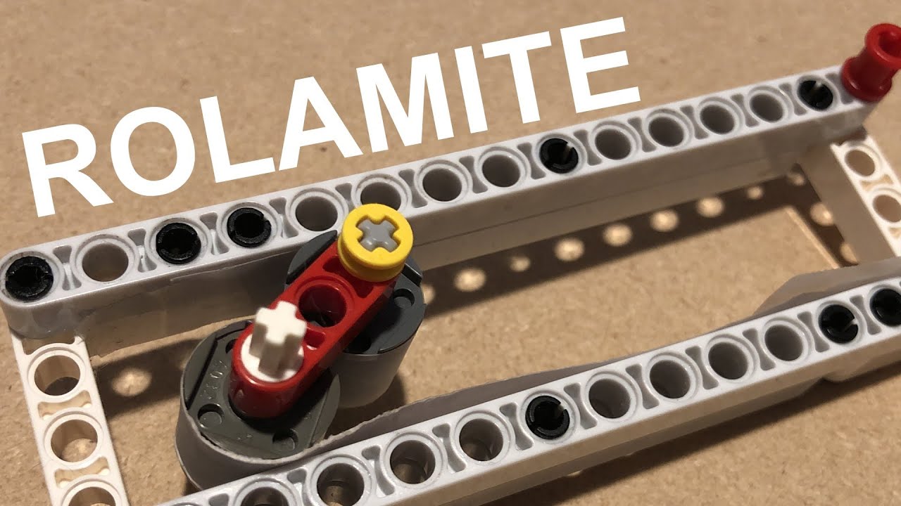
“The Amazing Rolamite — It Opens the Door for 1000 Inventions”

by

Norman Carlisle

One night in September 1966, a lean young, sandy-haired engineer named Donald Wilkes went into his garage workshop in Albuquerque NM to try an idea. What came out several hours later has been hailed as the first truly elementary mechanical invention of the 20th century.

Dubbed the Rolamite, it’s an almost frictionless bearing with countless applications in modern devices ranging from toasters to space vehicles. Engineers say it will take its place alongside the wheel, lever, and spring as a fundamental discovery of major significance.

Basically, the Rolamite consists of two rollers held in a track on opposite sides of an S-shaped band of springy metal, the rollers glide effortlessly in the track because the band moves with them as they roll along. Since the band and rollers are both moving at the same speed, there is no slip or drag between them and therefore virtually no friction. The device is so versatile it can function as a switch, a valve, a pump, a fuse, a thermostat, a force amplifier, a clutch, a speed changer, a brake, a pressure-sensing control, a solenoid, a fire alarm a — you name it and it’ll do it.

How could such a fundamental principle remain so long undiscovered? That was the first question I tossed at Donald Wilkes as I interviewed him recently in his equipment-crammed laboratory at Sandia Corp., the nuclear weaponry development center that Western Electric runs for the AEC.

“It’s hard to believe”, answered the 37-year-old inventor, who has been an avid PM reader since he was a boy. “The amazing thing is that a caveman has all the materials for making a Rolamite. Logs could have served for rollers and vines for the bands.”

So how had Wilkes come to invent the Rolamite? In the course of his missile work at Sandia, he had tinkered together a suspension system that particularly intrigued him. It consisted of a flexible metal band fastened in an S shape between two parallel surfaces. It was responsive to movements, all right — too responsive. “Wiggly and wobbly”, Wilkes describes it.

On that now-momentous night, Wilkes was relaxing in his living room when it hit him. How about putting rollers in the curves of the S? He jumped up and rushed out to his workshop. From his stock of scrap he fashioned a simple track and inserted a strip of beryllium copper he’d been carrying around in his pocket. From these components, he made the first Rolamite.

Now, Wilkes wondered, what would happen when he tipped the thing so that the rollers moved? Would the rollers slide along the curves of the band, or would the band move right along with the rollers with no slipping? Wilkes knew that if the band slipped he had nothing.

Again and again Wilkes tried it, his excitement growing. The rollers moved smoothly and the band went right with them. There was no detectable slip. The next morning he hurried to his lab to machine a more sophisticated model. Sensitive tests confirmed the observations made with the first crude model. There was no slipping and, therefore, little friction.

As development work went on, Wilkes and fellow researchers discovered that an almost infinite number of variations could be made by changing the shape, size and structure of the bands, rollers and tracks. Take the band, for example. So long as it’s under the same tension throughout its length, the rollers are stable at any point in the track. It takes just as much force to push them one way as the other way. But if you cut a slot in the band, you weaken it at that point, creating what is called a force bias — the rollers are made to “prefer” a particular point in the band.

To understand the effect of a slot in the band, think of the two loops of the S as springs that each exert a force against the other. Like a coiled watch spring, the band wants to lie flat and thus stores energy when it is forced to bend around the rollers.

When one of the loops is weakened by having a slot cut in it, the other loop overpowers it and “unwinds”, pulling the rollers with it. By cutting a long, tapered slot in the band, the rollers can be made to move the entire length of the track under their own power since the band becomes progressively weaker toward the widest end of the slot.

In a typical application, Wilkes visualizes a Rolamite with a slotted band to lick one common household annoyance — the leaky toilet valve. The leakiness usually results from the failure of the ball float and lever mechanism to generate enough pressure to close the water-supply valve. The force generated in a slotted Rolamite lever would close the valve with 30 times the strength of present valves.

Rollers can be Different Sizes

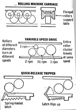
Wilkes’ first Rolamite used equal-sized rollers, but he soon found that one roller in a pair could be a giant, 10 or more times bigger than its companion. With rollers of different sizes, you get a remarkably simple speed changer that can be used in any number of mechanisms.

Perhaps the oddest discovery is that the rollers need not be round. Sandia researchers have tried triangular, hexagonal, oval and polygonal rollers. The basic principles of the Rolamite still apply just as with round rollers. The different shapes of rollers give the Rolamite many additional functions. For instance, a rectangular roller can be designed to lodge against a stop in a braking mechanism.

A lot of variations are possible in the track, too. For example, a track wider at one end makes the Rolamite a powerful force amplifier — energy is released when the rollers slip into the wider portion of the frame. This energy can actuate a variety of mechanisms, such as a firing pin or a switch.

There are other advantages, too. Many Rolamited devices would never need a drop of oil. Then there’s smoothness of operation. The steady, uniform operation of a Rolamite can take the jerks out of pop-up toasters, power sanders and a host of other devices.

There’s cost. Wilkes estimates that the Rolamite will actually reduce costs in 75% of its applications. The Rolamite does not require close tolerances, so they’re cheaper to make. Finally, there’s the all-around toughness. Extreme heat, cold or exposure to weather won’t affect Rolamite operation.

But, I wondered, doesn’t all that flexing of the band cause it to wear out eventually? Doesn’t metal fatigue cause it to break? Those were questions that bothered Sandia engineers too, at the beginning. Now they’ve quit worrying. The beryllium copper bands used in Rolamite have proved to be so sturdy that they show no sign of metal fatigue after 1,000,000 flexures. At that rate, the engineers figure, the band in a Rolamited home light switch operated 10 times a day would last 300 years. A Rolamited bathroom scale used five times a day would not wear out in 600 years.

You’ll never see the first applications of Rolamite because they’re tucked away in secret weaponry made by Sandia engineers. But hundreds of industries are embarking on crash programs to adapt the Rolamite.

Because Rolamite was developed with the help of tax dollars, it is available to the public. The Atomic Energy Commission will grant a royalty-free license for its manufacture to anyone interested. Wilkes himself now heads a new company set up to speed the Rolamite revolution along.

“We’ve just begun to scratch the surface”, Wilkes says. “Just wait until the independent inventors get going.”

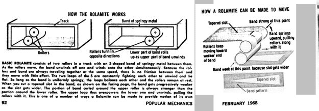
How the Rolamite Works
1pm1

Basic Rolamite consists of two rollers in a track with an S-shaped band of springy metal between them. As the rollers move, the band unwinds off one and winds onto the other simultaneously. Because the rollers and band are always traveling together at the same speed, there is no friction between them and they move with little effort. The two loops of the S are constantly fighting each other to unwind and lie flat. So long as the band is uniformly springy, the loops balance each other and the rollers remain at rest. When you cut a tapered slot in the band, the band gets progressively weaker as the slot gets wider. The portion of band curled around the upper roller is always stronger than the portion around the lower roller. The upper loop thus overpowers the lower one and unwinds, pulling the rollers with it. This is one of a number of ways a Rolamite can be made to provide motion of its own.
1pm3a

7 Likes
5 Likes

Here’s another one of my favorites; – it could prevent many infections, even epidemics. I first found it here:
Tannic acid utilized to “stain” odor-eliminating silver onto clothing

which links to: Rapid assembly of colorless antimicrobial and anti-odor coatings from polyphenols and silver J.J. Richardson et. al. Nature Scientific Reports,2022

What it does is make any water-tolerant surface permanently antimicrobial by using an invisible film of tannic acid a few nanometers thick which incorporates a bit of silver. Tannic acid has been used with black iron in iron-gall permanent ink for over a thousand years. Experiments over the past 120 or so years, especially the last 20 years, have shown that tannic acid can glue any metal (salt) ion to anything; silver and its compounds have long been known to be antimicrobial; so putting the two together was a natural idea. The materials cost is only about $1 for 100 square meters, figuring 10 mL/sq m.

Braindump:
The secret formula is: 0.1 mg/mL AgNO3, 0.4 mg / mL tannic acid in distilled water, either mixed fresh and used for immersion or applied as two separate sprays, with the silver nitrate applied first. Mixed, it should last a few hours. If it starts turning blown, it’s gone bad - no guarantees, but it may still work. The first few molecular layers of coating forms instantly on any surface, including the surfaces of spray droplets, so separate application of the solutions is preferred for spray applications. I The surface should be clean or the dirt will get coated. It works best on textiles, especially natural fibers, but may be used on any surface that can tolerate cleaning with water-based solutions. A rinse is usually not needed for thinly applied sprays, but rinsing may prevent later discoloration, particularly of residual silver nitrate not incorporated into the coating. Residues of dried cleaning agents on the surface, particularly bleach, may cause the coating to turn black or brown. It seems to be resistant to discoloration from cleaning products, but long-term behavior is unknown. The coating can be removed quickly with concentrated bleach, or more gradually with lower concentrations. On smooth surfaces, high abrasion will remove it.

On very smooth or high-wear surfaces it will not be permanent, but may be reapplied. In a single application, the film thickness is self-limiting to a few nanometers, but repeated applications will lead to a buildup, which is essentially the same as tea scum or “varnish”.

The coating seems not to act by releasing silver ions, it chelates the silver, so its activity should last indefinitely in most circumstances. This chelation makes it rather environmentally safe, but silver nitrate in larger amounts if released directly in a stream could kill desirable microorganisms.

Dry silver nitrate is hazardous, an oxidizer that will cause skin burns if touched (it is sometimes used for cauterizing in medicine). In the concentration used here, it is extremely safe, and could be ingested without problems. (Not recommended.) Silver nitrate in much higher concentrations was mandated by law in many jurisdictions in the US to be dropped in all newborn babies’ eyes.
/end braindump

The paper’s author, J.J. Richardson was (and may still be) trying to get a patent on the process, but it may have been for Japan and/or Australia only. I sent him prior art from the 1890s, search for “Tannin (gallotannic acid) in alkaline solution reduces silver nitrate” in the linked article (provided courtesy of Rex Research, see first post above). J.J. was trying to market the stuff at a literal million percent markup as a t-shirt underarm spray. :roll_eyes:

I tried to get a business off the ground making and marketing “Permanent Silver Invisible Ink Disinfectant” (“Silver Shield” would be better, but is somebody else’s trademark, unfortunately), but wasn’t able to raise any investment. There are many potential markets; I think most of the potential is in sales to institutions. I still have enough to make a couple thousand liters on hand. If anybody is interested, please contact me.

9 Likes
7 Likes

My Theranos scam-detector is pegged. I wonder whether they account for the need to add emissions controls:

5 Likes

The most popular YouTube comment: 99 percent this is a scam

4 Likes

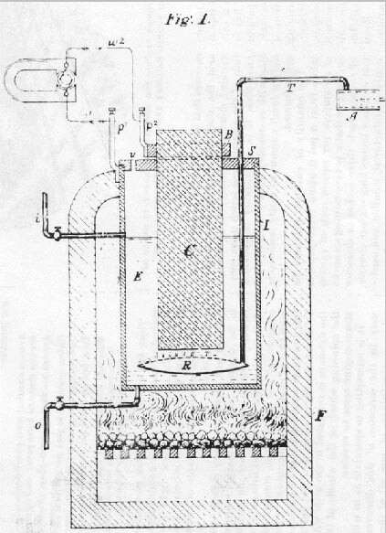
Similar scams have been around a long time. Here’s one from the 1890’s which was just a bit of mistake – he thought he had an 80% efficient direct coal → electricity electrochemical cell, but it turned out to be an 8% efficient thermoelectric.
image

“A carbon, C, is plunged into a solution of caustic soda, E. A pump, A, forces air into a perforated nozzle, R, which distributes the air uniformly in the electrolyte. The positive pole is fixed upon the iron receiver, I, containing the solution, and the negative pole [B] upon the carbon which is supported and insulated from the receiver by a collar, S. Two tubes, o and i, serve for the admission and discharge of the solution.”

The apparatus being put together as shown and the electrolyte having been brought to the proper temperature, the pump A is operated and air is forced into the electrolyte, causing a violent ebullition, which ebullition supplies to the electrolyte an excess of oxygen, brings fresh portions of the electrolyte continually in contact with the carbon, detaches the carbonic acid and ash formed on the surface of the carbon, and keeps the whole interior of the generator at a uniform temperature.

6 Likes

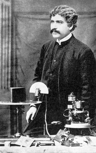
Sir Jagadis Chandra Bose, FRS invented not just radio, but millimeter-wave techniques in the 1890s. His inventions include semiconductors, detectors, waveguides, horn antennas, polarizers, adjustable attenuators, RF diffraction gratings, RF optics, and others.

Partial honors:
Companion of the Order of the Indian Empire (CIE, 1903)
Companion of the Order of the Star of India (CSI, 1912)
Knight Bachelor (KB, 1917)
Fellow of the Royal Society (FRS, 1920)

THE WORK OF JAGADIS CHANDRA BOSE:
100 YEARS OF MM-WAVE RESEARCH

D.T. Emerson
IEEE Transactions on Microwave Theory and Techniques, December 1997, Vol. 45, No. 12, pp.2267-2273. This WWW version has some additional photographs, and color images. Copyright held by the author and the IEEE.

In 1894, J.C. Bose converted a small enclosure adjoining a bathroom in the Presidency College into a laboratory. He carried out experiments involving refraction, diffraction and polarization. To receive the radiation, he used a variety of different junctions connected to a highly sensitive galvanometer. He plotted in detail the voltage-current characteristics of his junctions, noting their non-linear characteristics. He developed the use of galena crystals for making receivers, both for short wavelength radio waves and for white and ultraviolet light. Patent rights for their use in detecting electromagnetic radiation were granted to him in 1904. […]

In 1895 Bose gave his first public demonstration of electromagnetic waves, using them to ring a bell remotely and to explode some gunpowder. […] The first successful wireless signalling experiment by Marconi on Salisbury Plain in England was not until May 1897. […]

The wavelengths he used ranged from 2.5 cm to 5 mm. In his presentation to the Royal Institution in January 1897 … [note that Marconi was in attendance at this demonstration, and demonstrated nothing until several months later]


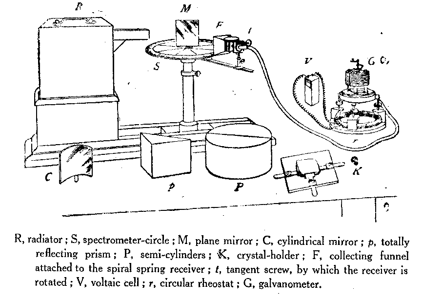
Figure 2. Bose’s apparatus demonstrated to the Royal Institution in London in 1897 [8]. Note the waveguide radiator on the transmitter at left, and that the “collecting funnel” (F) is in fact a pyramidal electromagnetic horn antenna, first used by Bose.


[Wikipedia: Jagadish Chandra Bose in the Royal Institution, London, 1897]


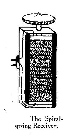
Figure 7. Bose’s diagram of his spiral-spring receiver used for 5-mm radiation.

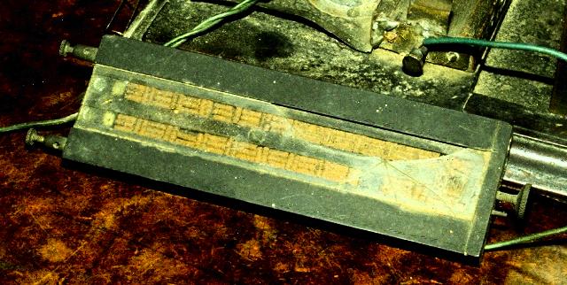
Figure 8. One of Bose’s free-space radiation receivers, recently described [3] as a “space-irradiated multi-contact semiconductor (using the natural oxide of the springs).” The springs are kept in place in their tray by a sheet of glass, seen to be partly broken in this photograph.


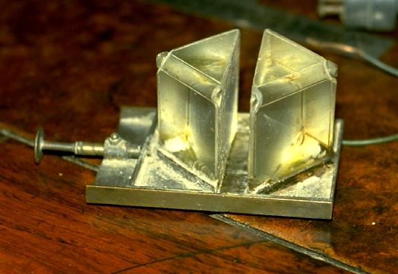
Figure 14. One of Bose’s original double-prism attenuators, with adjustable air gap.
[This design is still used in radio astronomy.]


Then he went a bit too far for conventional science, inventing a forerunner of the pen recorder and the oscilloscope, which he latercalled the “crescograph” (From his book; also see Wikipedia crescograph) which he used to gather data in support of panpsychism or hylozoicism, showing that not only animals, but plants and even metals demonstrated similar patterns of sensitivity or irritability, fatigue, recuperation, stimulation, depression and poisoning. Response in the Living and Non-living (1902)

5 Likes
4 Likes

That excerpt from Sudipto Das / Sudipto Sen seemed like a hit piece to me, lots of completely baseless assertions, others that are obviously wrong, e.g. that the double-prism radio attenuator was a quantum-tunneling device, or that he was ostracized later in life.

2 Likes

Their patent portfolio has only two published families. Others filed within the last 18 months would not have published.

2 Likes

The H3X motor looks good, though the balance of cooling system will lower the effective power/weight ratio. They’re aiming for 95% efficient (incl. inverter) @ 200kW continuous, 18.7kg, including gearbox (but maybe not inverter). The nice thing is the torque curve is flat and doesn’t drop off with voltage at practical RPMs, but to stay subsonic, prop diameter will be limited to a bit over 3 ft @ 200kW (750V) ; 4ft / 160kW / 600V ; 6ft / 111kW / 450V ; 8ft / 84kW / 300V. If they go to a 10:1 gearbox instead of 6.7, it will be more useful for larger props, which are inherently more thrust / power efficient.

Siemens had 5kW/kg in 2015. Equipmake can do 4.6 - 5.2 kW/kg for a system including 5.5:1 reduction gearbox (10kRPM : 1800RPM), at 96%-97% efficiency at that output. But, as always with these things, that’s not continuous power, which is about 120kW @ 1100RPM, though the efficiency should stay over 95%. But you can actually buy them, and they’re engineered for automotive durability.

The problem is that electric motors don’t produce power, they convert it. The figures never account for the power production, the cooling, the controller electronics; the efficiency quoted is almost never at the operating condition, the power is not continuous power etc. Electric aircraft are never going to have the range of a conventional plane at similar payload. Superconducting motors, liquid hydrogen fuel, high performance fuel cells - that could come close, but operationally it’s impractical. Electric motors, like batteries generally have incremental improvements, not big leaps in performance.

The cooling for these things is going to sap net efficiency dramatically - heat transfer from a radiator is hard to decouple from drag. I have a potential way to use the propeller as the radiator, derived from a Sandia spinoff (heh) application to computer cooling fans, which runs the heat flux through a thin, high-shear layer of an air bearing. I have other schemes for improving compressed air thermal power efficiency, e.g. for tip-jet props, but might be patentable, so I’ll stay mum.

My favorite power transmission invention is Steven Salter’s digital displacement pump, used in the Flowcopter.

Edinburgh’s Flowcopter has a different solution entirely. Its heavy-lift cargo drones will run aviation-certified combustion engines, and these engines will drive Digital Displacement pumps repurposed from the off-road and industrial vehicle markets, to run hydraulic motors at the props.

These pumps are able to distribute and regulate hydraulic flow between a number of different outputs, under digital control, with the kinds of near-instant response times you need to balance a drone in flight. Each hydraulic motor will deliver up to an enormous 96 kW (129 hp) of power, while weighing just 5.5 kg (12 lb) and costing less than US$1,000 apiece. Flowcopter says “nothing electric comes even close.”

I tried to sell the Flowcopter team on a tandem-helicopter design, which I still think would be a lot more efficient than a quad-rotor, having bigger rotors, fewer motors and less control complexity (though with more complex helicopter-style hubs.)

5 Likes

Patrick Boyle humor:

3 Likes

LOL. Clearly there’s a big market for ideas VCs can understand. Dumb ideas. Amazingly dumb ideas, not like Bill Beatty’s brilliantly dumb ideas.

Example:

Kindergarten Solar-powered Death Squad

Take a large crowd of children out into the sunshine and give each one a 20cm square mirror. Show them how to aim all of their little spots of sunlight at the same distant object, then stand back and see what they do. Better yet, run away.

FAST!

Duck-plunge Mechanical Fountain

When a large rock is flung into a pond, the waves spread into a series of ripples of descending wavelength, as if the water has “Fourier Transformed” the splash signal. It has! The water surface is not a linear medium, therefore any signal becomes “chirped” in a similar way to the “whistlers” produced in ELF radio sets by distant lightning pulses. If you could wiggle an underwater object and produce an “antichirp” series of ripples, (a temporally-reversed version of the ripples from a big splash,) then as the ripples moved, they would slowly compress together and finally create a line or circle with a little explosion of spray.

Ripples also take the form of an expanding circle. Rather than just reversing the “chirp”, we could also reverse their direction. If water ripples could be created as inwards-curving rings, so that they focussed themselves to a point, so much the better.

Therefore build a bicycle-powered wave generator which can be placed at the shore of a pond. It would slowly vibrate a long, curved wall which floats half-immersed in the water. When aimed at a distant unwary duck, a series of ripples is created. The duck sees the distant ripples approaching, and contracting, and concentrating, then… DOOOSH! WAAAK-Aaak quaaak quackquack…

I have adapted this to arbitrarily-arranged multi-megawatt wave-powered compressed-air-energy-storage phased-array duck-disruptor systems, which I intend to test as soon as I can locate a sufficiently large supply of hyphens.

5 Likes

Here is one of my favorite designs, which didn’t work at all for its intended purpose to increase sea evaporation, in fact it dramatically suppressed it by cooling large areas downwind – but his idea for how to make a cubic-meter per second sprayer is useful for so many things . (I have an enormously simpler design for boundary-layer disruptors to increase evaporation, if anyone were interested.)

SPRAY TURBINES TO INCREASE RAIN BY ENHANCED
EVAPORATION FROM THE SEA
Stephen Salter
Division of Engineering, University of Edinburgh
Mayfield Road, Edinburgh EH9 3JL, Scotland
S.Salter@ed.ac.uk
Pre-print for the tenth Congress of International Maritime Association of the Mediterranean, Crete, May 2002.

image
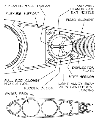
Figure 3. A section through the exit nozzle showing the coil
spring embedded in a block of rubber with four stiffening
springs. Sections can be individually removed

a one-metre cube of water at the sea surface would have its surface area increased by 200,000 times if it were split into 30 micron drops. [. . . .]

The surface tension of sea water is about 0.078 N/m, a little higher than that of fresh water. The power to create the enlarged area for 30 micron drops is just over 15 kilowatts for a cubic metre per second[. . . .]

the exit area is 0.015 square metres, equivalent to two round nozzles 100 mm in
diameter. To get this exit area with a nominal slit width of 30 microns will take nearly 500 metres of nozzle length, every bit of which must be varied in width to an accuracy of a few microns. [. . . .]

The proposed solution makes use of the behaviour of coil-bound tension springs as shown in figure 3. If the wire of a spring is twisted as it is wound onto a mandrel, the resulting torque will tend to close the spring so that adjacent coils touch.

If the coil is stretched the gaps will open to provide a long slit with the well-rounded approach path needed for an efficient nozzle. Despite this, the viscous losses through the narrow exit will contribute more to energy losses than the feed pipes.

We can make a directional exit nozzle by embedding the coil-bound spring in a block of stiff rubber and then stretching the rubber to open the gaps between coils. We can
control the stiffness of the rubber by embedding further springs with smaller coil diameters wound with thicker wire. A 1.5 mm wire wound into a 110 mm coil with a 45 degree exit angle gives the nozzle area needed. The openings of each gap will depend on the local section thickness and elastic properties of the surrounding rubber and springs. It is desirable that they should be consistent along the length of the coil. Sections of coil about a metre long can be separately adjusted to set drop diameter and flow rate so as to get the chosen tip speed ratio. The internal pressure will produce a large force tending to stretch the assembly and so control can be exercised with a central pull rod which closes the spring against the internal pressure.

The short path and the very small nozzle gap means that flow will be laminar. According to Bernoulli there will be a drop in pressure as water gains velocity toward the exit. Any reduction in the slit width will reduce the local velocity, allow the local pressure to rise and so tend to restore the position of the coil. This means that we can use coils which would seem very weak springs. We can notch the wire to induce jet break up.

When we take into account all the pressure drops caused by change of height, pipes, nozzles and surface tension, the final exit pressure in an 8 metre per second wind will produce a jet velocity of about 42 metres per second relative to the blade. This is less than the 45 metres per second blade speed, leaving a net velocity relative to the ground of 3 metres per second. This loss of kinetic energy means a further loss of just under 4 kilowatts but helps to spread the spray.

Liquid sprays are used in many branches of chemical engineering and some applications demand accurate size control. Unfortunately it seems that most round nozzles designed for high flow rates produce rather a wide range of drop sizes,
perhaps because flow is turbulent. This must be avoided because the larger drops will not have time to evaporate and the smaller ones will produce salt fallout. The plan is to control drop diameter by generating a high frequency (about 1MHz) ultrasonic signal from a piezo-electric element at the centre of the jet coils. Only a few kiloPascals will be needed to overcome surface tension. [. . . .]

We often think that electrostatic forces are small but they are large compared to other forces on small drops. The spray coils would be made of a material which can be covered by a tough electrical insulator such as the hard anodic film on titanium. (We are doing initial experiments with enamelled copper wire). The metal of the coil inside the insulator would be held at a potential of, say, -300 volts relative the sea. The column of water from the sea along the pipes and into the coil will have low electrical resistance and so the water in the nozzle gap will be at nearly zero volts. However, the electrostatic field from the coil wire will attract positive charge to the water surface. If a drop of water is still in the field when it breaks away from the
connection back to the sea, that charge will still be there. It will repel any other charged drop with a force depending on the product of the two charges and the inverse square of distance.

Apart from insulation leakage no current will be drawn from the 300-volt source but, at our design wind speed of 8 metres per second, there will be a current of 24 amps for both blades. The power to charge the drops comes from extra pressure needed to eject them and is about 3.5 kilowatts.

The various power consumptions for a wind speed of 8 metres per second and an effective [“eggbeater”, vertical axis] turbine area of 1000 square metres with a performance coefficient of 0.35 are tabled below.

Power kW %
Power from the wind 107.5 100
Lifting water for 10 metre release 67 62.3
Pipe and bend losses 4.7 4.4
Viscous nozzle losses 18 16.7
Surface tension 10.4 9.7
Electrostatics 3.6 3.3
Kinetic exit loss 3.8 3.6

Table I. Power estimates for the various part of the system.
At this wind speed the output of water would be 0.67
cubic metres per second.

That’s 40.5kW/(0.67 cu m/s) for the sprayer, = 60.4 J/L = 60.4 kPa = .604 bar pressure. By comparison, the energy content of gasoline is 32 MJ/L.
There would be 7e13 30-micron droplets per cubic meter, with a total area of 200,000 square meters.
These would be charged to 300V initially, and the current from the flow of charged droplets in the wind would carry 24 amps of current. (If the droplets can be forced to rise in an updraft, the voltage would go up 300V for every multiple of the release height by capacitive voltage multiplication, as in a Van de Graaf generator. If used for this purpose, one would use lower release heights and higher initial voltages, making a potentially very efficient ~100-MV generator of any desired power, even 10s of GW.)

By various means, which I’ll share with whomever wants to pay to patent the idea,
direct wind → electric power generation becomes possible
far in excess of the 107kW sprayer power, and having an effective “rotor” area many times larger than the device, which can be engineered to provide whatever DC voltage is desired.

The core spray device produces about 3.33 sq m of droplet surface area per second per watt, or 12 sq km / hr / kW.

The whole 107kW device releasing at 10m height will have the droplets settle out within 6 minutes, producing over 83 acres of droplet surface area per horsepower, or nearly 12,000 acres (48 sq km) total evaporation area at any given time.

There are many other economically important applications of high-volume spraying, some of which you might guess, but all of which I’ll keep to myself pending a grantor or investor stepping forward. Prof. Salter died this year and his design was published over 20 years ago, so the basic design is open – but these applications, methods and larger systems are very likely to be profitable not only to use, but even to patent and license, which is rare.

4 Likes

Here we have a couple of recent patents regarding exotic space propulsion techniques:

https://ppubs.uspto.gov/pubwebapp/authorize.html?redirect=print/pdfRedirectDownload/11818829
https://ppubs.uspto.gov/pubwebapp/authorize.html?redirect=print/pdfRedirectDownload/12160188

1 Like