This NASA film from the 1960s chronicles development of the Saturn I rocket from the origins of U.S. rocketry through its first suborbital launch (with dummy upper stages and payload) on October 27, 1961. The Saturn I was, at the time, the heaviest lift U.S. booster in service, but its payload to low Earth orbit, 9100 kg, was less than today’s Falcon 9 which, with recovery of the first stage, can orbit 15,600 kg.
This harkens back to an innocent time, before NASA’s mission became diversity, inclusion, equity, etc. I suppose, the success of the Saturn program helped the public establish belief in the competence of the technocratic/bureaucratic state. It was a major error, however, to conflate mastery of materials and things to heading society toward the promised utopia.
Watching the video, I was made curious about the gimbaling of rocket engines. Controlling movement during generation of such thrust forces pushing against the rocket body must present some challenging engineering problems.
Indeed: all of the force generated by the engine needs to be transmitted through the gimbal bearing at the top of the thrust chamber. There are usually hydraulic or electrically operated pistons connecting the fixed structure to the thrust chamber that allow moving it and the nozzle in two axes. Note that this means the fuel and oxidiser feed lines must be flexible to cope with the motion of the thrust chamber. All of this adds weight, complexity, and potential failure modes, so in some rockets such as the Saturn I and Saturn V, only the outer four engines were gimballed with the centre engine(s) fixed. In the Starship, only the inner engines gimbal, with all of those on the periphery fixed.
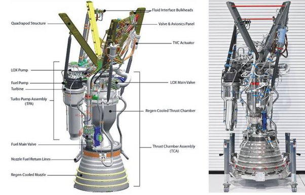
Here is a diagram of the Falcon 9 Merlin engine showing the attachment of the thrust chamber to the stage structure and the gimbal pistons (labeled “TVC [thrust vector control] Actuator”).
This, too, provokes some wonderment. Given the weight constraints and consequent need for booster skins to be thin, application of such massive forces - whether via gimbal bearings or directly to what I imagine is semi-monocoque construction could literally tear the whole thing apart if the forces are not somehow spread over the entire skin. Figuring out how to do this must have involved some trial and error (RUD’s).
Rocket engines are usually mounted to a “thrust structure” which transmits the force from the engines to the structural skin of the stage (which, in most modern rockets, doubles as the wall of the propellant tanks). Here is a cross-section of the bottom of the second stage (S-II) of the Saturn V.
The stippled vaguely ‘W’ shaped component with the annotation “See Detail A” is the thrust structure. This drawing also shows that the centre engine lacked the gimbal bearing, actuators, and flexible propellant feeds of the outer engines.
The first stage (S-IC) had a similar configuration. Its thrust structure was, at 22 tonnes, the heaviest single component of the Saturn V.
It really was a different world back then. NASA could build a new rocket in little more than 3 years, filling all sorts of new needs along the way. (Woops! We need a lubricant that works in a vacuum!).
Today, NASA can’t do that – but SpaceX can. In a rational world, the decline in NASA’s ability to accomplish things in a timely manner would be the subject of serious investigation – and corrective actions would be taken. In a rational world.
")