Begging the indulgence of esteemed colleagues, whose critique of my prior post about UFO technology, brought a quick and merciful death to that line of inquiry, below will be another line of inquiry; but first a brief digression:
The SOL conference held at Stanford University recently is worth scrutinizing if for no other reason than that we now have Senator Chuck “Six Ways From Sunday” Schumer putting his name behind “disclosure”; and this midst cultural turbulence that borders on the Apocalyptic. So one should scrutinize this for disinformation that occludes valuable information.
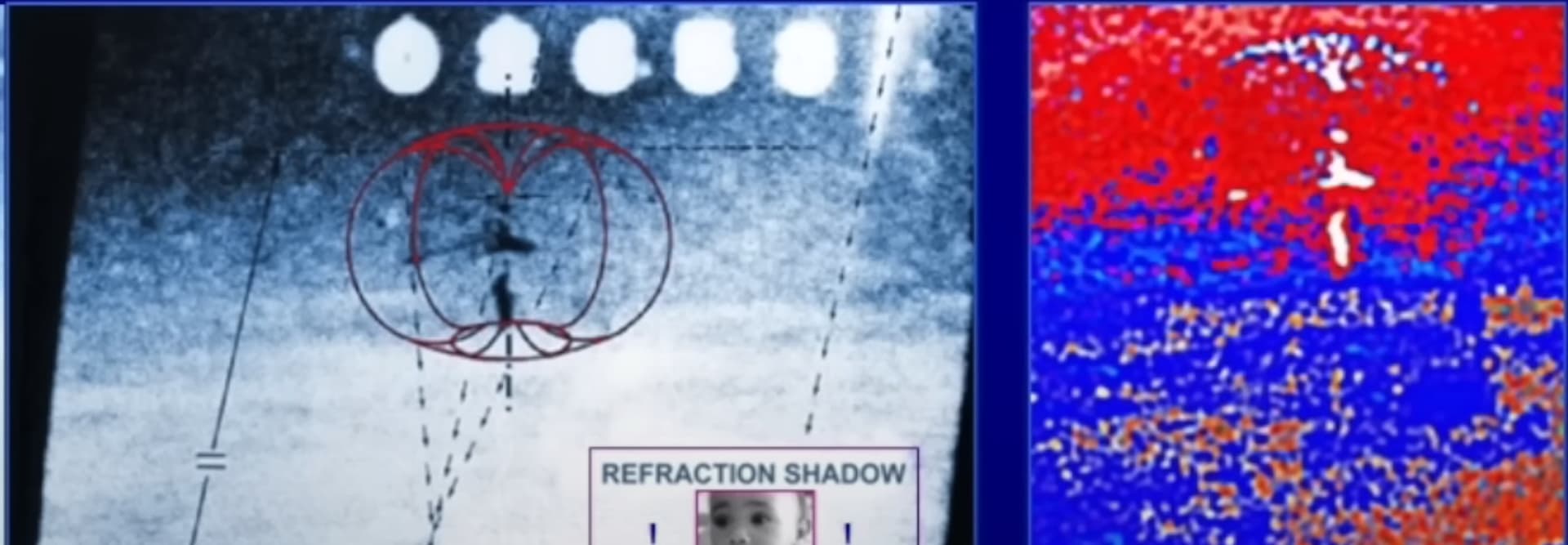
During the due diligence, resulting in the mildly embarrassing dispatch of the “rings” of an image and its interpretation by Ray Stanford (of whom I knew nothing previously) his below-linked photo appeared more likely to be fruitful. So I asked myself, why was it that Knuth chose the most embarrassingly easy-to-debunk photograph and ignored Stanford’s other photographic evidence that point to physical interpretation?
I’m suspicious that whoever is doing the physics consulting for this chain of evidence decided to promote the most embarrassing photograph to draw attention away from Stanford’s more informative photographs that apparently go clear back to 1950s research into what Stanford calls “MHD propulsion” but which I suspect is Electrohydrodynamic propulsion for reasons I get to at the end of this article.
I’m not saying Knuth is a disinformation agent despite his claim to physics credentials that should have alerted him to the fact that the Stanford photograph he presented at the (ahem) Stanford Conference was embarrassingly wrong. But I am saying that, for reasons that will become apparent, Stanford – Ray Stanford – may be on to something but not have the right physical interpretation: Something the government wants kept secret even to this day.
Popping the stack, let’s dive in:
Stanford’s above more credible photograph (than the Newton’s Rings) indicate a toroidal flow of charge – plausibly electrons out of the top to produce negative ions that entrain large mass flows drawn around and down providing vertical thrust before the electrons are stripped to come back into the anode at the bottom, leaving the neutral air molecules with a net downward motion. The larger the potential, the more dispersion of electrons into a larger volume of the atmosphere hence the more entrained mass hence the more fuel efficient.
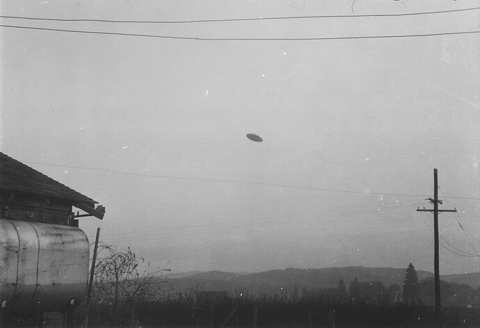
Take for example this famous McMinnville UFO photograph from 1950:
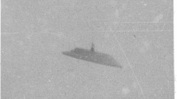
The tower at the top could be emitting negative ions from the tip that would curve around the sides to be discharged on the flat plate on the bottom.
And, indeed, the witnesses claimed that a blast of wind hit them when the bottom turned toward them:
Note, this was a decade before Townsend Brown’s controversial claims of an ionic wind vehicle that he is supposed to have demonstrated at model scale.
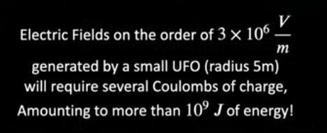
Caveat emptor this quote from Knuth on what it takes to ionize the air around a UFO:
Taking this at face value for the moment:
Burning gasoline at a rate of 1.5kg/s it takes about 13s to reach 1GJ energy.
The more mass you can entrain with a given amount of energy, the more thrust per energy. So it makes a lot of sense that the charge repulsion at the top would expand outward to a huge area to entrain a lot of air mass. I don’t know what kind of effective fuel efficiency this would result in but it is plausibly far greater than blades.
Which brings to mind something Jacques Vallee said to a friend of mine about witnessing a UFO in France: “It just sat there like a rock doesn’t.” That quote comes to mind because in the limit of infinite entrained mass flow, one is in a similar energy efficiency regime to standing like a rock on solid ground.
OK so this brings me to a wild speculative idea that’s been haunting me for some time about using rocket engines to create megavolt potentials – and it is based not on MHD but EHD – electrohydrodynamic electrical generation.
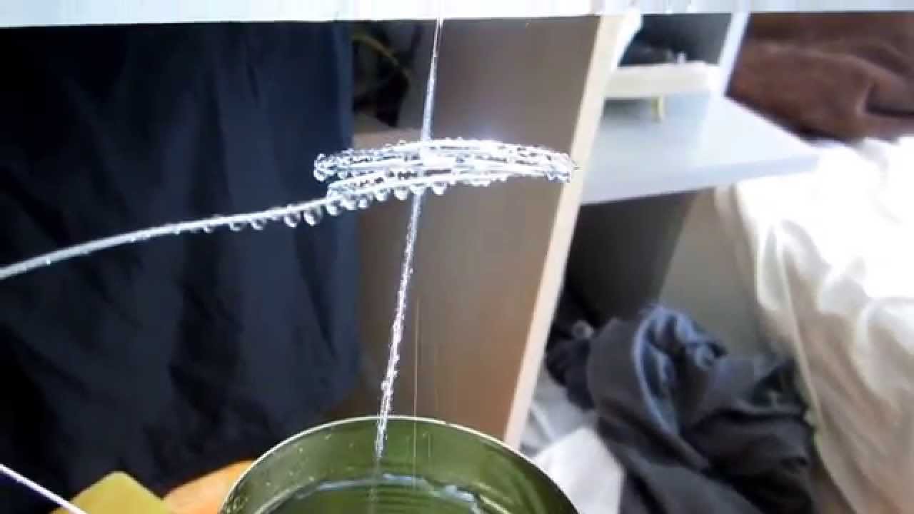
It is basically a rocket engine driven Lord Kelvin’s Thunderstorm.
Notice as charge builds up in the cans the water starts behaving erratically. At the extreme, the drops first spread then levitate before the spark discharge.
The voltages attained are enormous because in order to achieve small voltages, you need to attach a large amount of charge per mass to the rocket exhausts – and that’s hard to do. So you end up with a specific charge that is too low to produce anything but megavolts of potential. This is because in order to bring the mass to a rest you have to have high enough charge on the destination to repel the same-charged particle to a standstill. Less charge on the particle per mass, the greater the charge on the destination plate to bring that particle to rest.
Using water injection one can dramatically increase the combustion efficiency of a rocket motor and at the same time bring its temperature down such that during the expansion and cooling in the bell it changes phase sometimes to even ice crystals. The idea depends upon that change of phase to at least liquid if not solid. This may permit maintaining a low pressure in the expansion area while getting rid of the mass in a more convenient form.
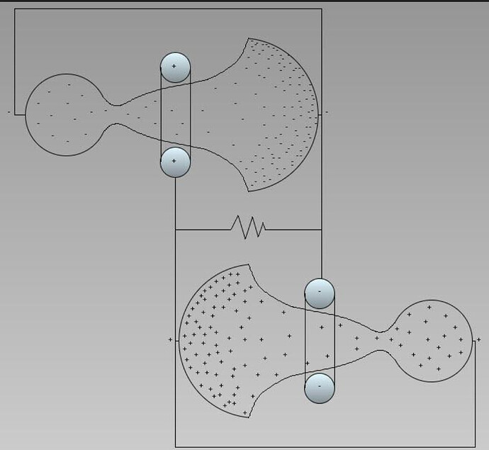
I’m not sure this is a correct drawing of the setup but it’s something I threw together to give the general idea:
The resistor is the air surrounding the UFO.
Now, there’s some red meat for our esteemed colleagues to chew on.
