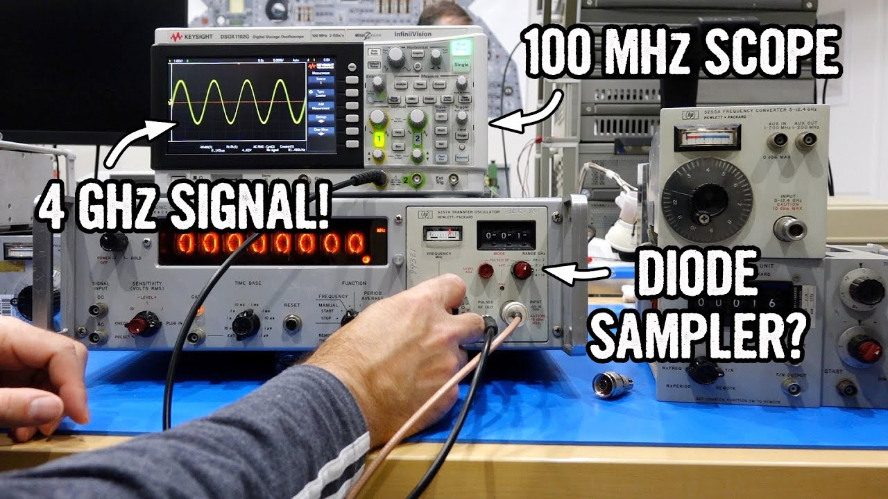
Sampling of repetitive waveforms is an almost magical way to extend the frequency range of electronic test equipment such as oscilloscopes and frequency counters to far beyond their native upper limit. A sampling circuit was at the heart of the Hewlett-Packard 5257A Transfer Oscillator, repaired in the post of 2023-09-25. But how is this black magic achieved? And, in particular, how did electronics gear made in the 1960s achieve sub-nanosecond time resolution when sampling analogue signals?
All is revealed in this deep dive into sampling circuits, including the extraordinarily clever trick of using a tunnel diode as an analogue signal switch and what appears to a casual schematic reader as a dead short circuit as a signal reflector in the microwave domain.
I remember when, in the summer of 1968, while working on an avalanche transistor driver for a semiconductor laser data link, I was allowed to use a Tektronix 1S1 sampling unit to measure nanosecond-scale rise time of pulses we were generating. Introduced only three years before, in 1965, the 1S1 had an almost mythical status, much like the Holy Hand Grenade of Antioch, and as a larval engineer I felt honoured to be entrusted with such device.


