Ispace HAKUTO-R Lunar Landing Attempt

On 2022-12-11, the ispace HAKUTO-R M1 mission, a private Japanese mission to land on the Moon, was launched on a SpaceX Falcon 9 from Cape Canaveral Space Force Station in Florida. See the post here “SpaceX HAKUTO-R M1 and Lunar Flashlight Launch” from 2022-12-20 for details.

After a roundabout path to the Moon, minimising the energy required to match velocities and enter lunar orbit, the spacecraft will attempt to land on the lunar surface in Atlas crater in the northeast quadrant of the near side.


If the landing is successful, plans are to deploy the Emirates Lunar Mission Rashid rover which the lander carries along with its own scientific instruments.

This is the first privately-funded spacecraft to attempt landing on the Moon, and the first Japanese lunar landing mission. The live stream covering the landing attempt is scheduled to start at 15:20 UTC on 2023-04-25.

5 Likes

The Webcast of the landing is now live. At 15:45 UTC, the spacecraft is behind the Moon and should be performing its deorbit burn. Acquisition of signal is expected around 16:15 UTC as the lander emerges on a course to its landing site.

4 Likes

Lander has reappeared behind the Moon and braking burn is underway. Altitude is 25 km, down from 100 km orbit at the start of the landing sequence.

3 Likes

This is a picture taken from HAKUTO-R during the total solar eclipse of 2023-04-20. You can see the shadow cast by the Moon on the Earth as it rises above the Moon.

hakuto_a_2023-04-25

4 Likes

15 minutes after touchdown time - Long silence - live commentary interrupted, gone to videos of mission. We don’t know if there is still a data stream. Didn’t see any happy faces when last we saw the controllers.

3 Likes

Takeshi Hakamada, ispace CEO: “We have to assume that we could not complete the landing on the lunar surface.”

Communications were received right up to the expected time of landing, but nothing since then.

3 Likes

The Webcast ended with a statement that they were continuing to analyse data to determine what happened. If, as appears likely, the mission is lost, Japan will join the Soviet Union, U.S., Israel, and India in failing to land on the Moon on the first try. The only country to successfully land on the Moon on the first attempt is China, with Chang’e 3 on 2013-12-01.

(The situation for the U.S. is somewhat complicated. The first U.S. soft lander, Surveyor 1, touched down successfully on the Moon on 1966-05-30. But three earlier U.S. hard landers on Rangers 3, 4, and 5, all failed when the impactor spacecraft which was to carry them near the surface failed. The Ranger landers were balsa wood spheres with a braking engine that would slow them before thumping down on the Moon’s surface. They were considered landers, and none of the three succeeded.)

6 Likes

Balsa wood is quite an interesting topic on its own!

Because it is low in density but high in specific strength, balsa is a very popular material for light, stiff structures in model bridge tests, model buildings, and construction of model aircraft; all grades are usable for airworthy control line and radio-controlled aircraft varieties of the aeromodeling sports, with the lightest “contest grades” especially valuable for free-flight model aircraft. However, it is also valued as a component of full-sized light wooden aeroplanes, most notably the World War II de Havilland Mosquito.

Balsa wood is often selected as a core material in composites. Because O. pyramidale grows quickly and tolerates poor soils it is lower in cost per performance compared to polymer foams like EPS while having better tensile strength than typical foams. For example, the blades of wind turbines are commonly constructed of many balsa plywood cores and internal spars covered with resin infused cloth on both sides. In table tennis bats, a balsa layer is typically sandwiched between two pieces of thin plywood made from other species of wood. Balsa wood is also used in laminates together with glass-reinforced plastic (fiberglass) for making high-quality balsa surfboards and for the decks and topsides of many types of boats, especially pleasure craft less than 30 m in length. On a boat, the balsa core is usually end-grain balsa, which is much more resistant to compression than if the soft balsa wood were laid lengthwise.

5 Likes

Here is an article from Smithsonian magazine which describes the Ranger “Lunar capsule”.

But the JPL engineers knew that solid rockets, while simpler than liquid-fuel ones, were also more unpredictable. No one could be sure a solid rocket would deliver the amount of braking needed to counteract all of the lander’s excess speed. Furthermore, nobody knew how to predict precisely how fast the spacecraft would be going relative to the moon, or even the exact location of the moon itself.

With all these uncertainties, Burke figured that Ranger might strike the moon at speeds up to 200 mph. He and his team began talking about developing a rugged spherical capsule capable of withstanding such an impact. If this “survival package” seemed a less than elegant plan for humanity’s first landing on the moon, Burke didn’t mind. “All we were thinking about,” he says, "was ‘Let’s get a transmitter down so we can prove we’re there.’ "

But how to protect sensitive scientific instruments from a crash as violent as an Indy race car hitting a concrete wall? To identify the best energy absorber, a variety of materials, including aluminum honeycomb, cardboard, and, in Burke’s words, “anything crushable,” were subjected to tests such as being dropped from a helicopter and slammed around with laboratory equipment. The victor, by a surprisingly wide margin, proved to be blocks of balsa wood, oriented with the end grain radiating out around the sphere for maximum energy absorption.

By the summer of 1960, a 26-inch-diameter sphere weighing 92 pounds began to take shape at a division of the Ford Motor Company in Newport Beach, California. Attached to the capsule would be a solid-fuel retrorocket, which was to ignite when Ranger was 10 miles above the moon. Ten seconds later, after slowing the lander almost to a hover, the rocket would burn out and be cast off. Pulled by the moon’s gentle gravity, the sphere would fall the remaining 1,100 feet to the surface, striking at a speed of about 75 mph. Cushioned by a six-inch layer of balsa wood, the lander would bump and roll to a stop. Inside, floating on a thin layer of water, a one-foot-diameter fiberglass sphere containing a seismometer, radio, and batteries would right itself and begin transmitting.

After three consecutive failures (all of which occurred before the landing capsule even had a chance to be tried), Ranger was redesigned into a pure impactor with six cameras, deleting the hard landing capsule. The first two of these failed as well, with the first success being Ranger 7, which impacted the Moon on 1964-07-31 at 13:25:48.82 UTC (love that precision!) at a velocity of 2.62 km/sec.

Here is contemporary newsreel coverage of Ranger 7. The lunar photo quality is what we saw at the time. Years later, the data were re-processed digitally and higher quality imagery was extracted. The spacecraft shown at the start of the newsreel is a Ranger, but not Ranger 7—the one shown has the landing capsule, which was deleted on Rangers 5 and later.

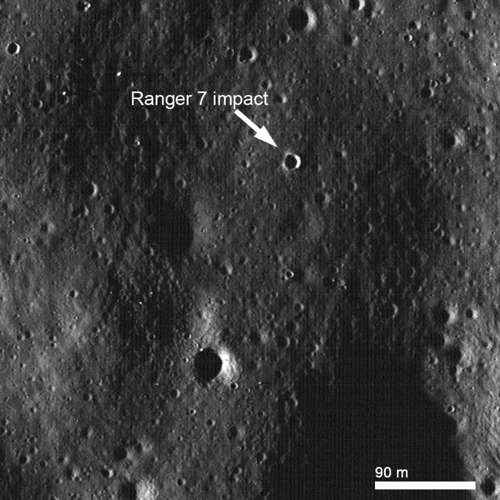
Here is the crater made by Ranger 7’s impact on the Moon, imaged by Lunar Reconnaissance Orbiter in 2018.

5 Likes

A group of radio amateurs monitored telemetry signals from the HAKUTO-R spacecraft during its lunar landing attempt and have published an analysis of the final moments before impact.

image

During 6s around ‘E’ the spacecraft is spun up axially to 40 rpm. This is detectable in the frequency trace. It shows a sinusoid with frequency wobble of 78.6 Hz pk-pk. In the AirSpy display, the signal strength can also be seen pumping up and down in amplitude 5 dB with a period of 1.5s (40 rpm). This is due to minor variations in the antenna beam pattern and possibly shading.

The spin-up occurred quickly at ‘E’. This may have been deliberate, or it may have been a consequence of erratic motor/thruster behaviour. Deliberate choice seems the most likely.

A diffuse signal becomes gradually visible just to the right of the residual carrier. From this observation an estimate of vertical velocity can be made.

The signal is 15–20 15 dB lower than the carrier and the separation increases over time. At LOS it occupies a bandwidth of some 5 kHz.

This phenomenon is compatible with reflection of the carrier off the Moon’s surface, as reflections would have a different Doppler shift compared to the direct line-of-sight signal.

The Moon’s surface is rough, so the reflected energy fluctuates rapidly as to frequency and amplitude, being the sum of an infinity of elementary reflections.

Because the energy is diffuse, there is no specific frequency to record for this phenomenon. Roughly the median is perhaps 3.7 kHz at LOS, equivalent to a velocity difference of 130.6 m/s as resolved along the line-of-sight to Earth.

Assuming the descent is vertical (i.e. has no horizontal component of velocity), that along line-of sight speed can be resolved to a vertical speed of 148 to 161 m/s. The spread is due to slight uncertainty in location on the Moon.

Now 88s of free fall alone would achieve a vertical velocity from g = 1.624 m/s² of 143 m/s.

The signal ceases abruptly at 16:45:09 utc when HAKUTO hits the Moon.

From stationary, an 88s freefall drop covers 6.3 km. 88s of the existing downward speed at E will add to that drop altitude.

A spectacular epitaph is recorded in [the plot below] , the result of hours of painstaking research by EB3FRN.

3 Likes

On 2023-04-26 NASA’s Lunar Reconnaissance Orbiter Camera (LROC) imaged the HAKUTO-R impact location.

Here is an animated GIF showing before and after views of the impact site. The Sun angle is different in these two images, accounting for the change in the appearance of the craters that appear in both.

2 Likes

Ispace have released their analysis of the HAKUTO-R landing failure.

On April 26, 2023, at 00:40 Japan Standard Time, the lander began the descent sequence from an altitude of approximately 100 kms above the lunar surface. At the end of the planned landing sequence, it approached the lunar surface at a speed of less than 1 m/s. The operation was confirmed to have been in accordance with expectations until about 1:43 a.m., which was the scheduled landing time.

During the period of descent, an unexpected behavior occurred with the lander’s altitude measurement. While the lander estimated its own altitude to be zero, or on the lunar surface, it was later determined to be at an altitude of approximately 5 kms above the lunar surface. After reaching the scheduled landing time, the lander continued to descend at a low speed until the propulsion system ran out of fuel. At that time, the controlled descent of the lander ceased, and it is believed to have free-fallen to the Moon’s surface.

The most likely reason for the lander’s incorrect altitude estimation was that the software did not perform as expected. Based on the review of the flight data, it was observed that, as the lander was navigating to the planned landing site, the altitude measured by the onboard sensors rose sharply when it passed over a large cliff approximately 3 kms in elevation on the lunar surface, which was determined to be the rim of a crater. According to the analysis of the flight data, a larger-than-expected discrepancy occurred between the measured altitude value and the estimated altitude value set in advance. The onboard software determined in error that the cause of this discrepancy was an abnormal value reported by the sensor, and thereafter the altitude data measured by the sensor was intercepted. This filter function, designed to reject an altitude measurement having a large gap from the lander’s estimation, was included as a robust measure to maintain stable operation of the lander in the event of a hardware issue including an incorrect altitude measurement by the sensor.

4 Likes

Scott Manley analyses the crash of HAKUTO-R on the Moon, including his simulation of the landing attempt in Kerbal Space Program.

3 Likes