The Curious World of the 8 Inch Floppy Disc

IBM originally developed the floppy disc as a read-only medium used to distribute microcode for their mainframe processor and peripheral products. The goal was a medium with sufficient capacity for the application, a compact and inexpensive drive, and affordable media cost. The original design was an 8 inch single sided disc in a protective cover storing 81 kilobytes, first shipped in 1971 as part of the 3835 Storage Control Unit and patented in 1971 (3,668,658 [PDF] disc medium, 3,678,481 [PDF] drive). The potential of the floppy disc as an alternative to slow and cumbersome media such as tape for applications such as word processing and data entry (replacing card punch machines) was quickly appreciated within IBM and by other vendors, and the format evolved into read/write drives whose capacity grew through the 1970s, with IBM introducing a 1.2 megabyte double-sided, double-density floppy disc format in 1977. Floppy discs, though expensive, were the only medium that could provide a vaguely convenient user experience on the emerging microcomputers of the first generation of personal computing, and were widely adopted by systems such as CP/M.

While 8 inch floppy and drives were small and inexpensive by IBM mainframe standards, they were large and costly in the context of home and office computers intended to sit on a desktop. This led to the development of the 5¼ inch minifloppy in 1976 and the Sony 3½ inch microfloppy in 1981. When the IBM PC shipped with 5¼ inch floppy drives in 1981, the smaller size rapidly became the standard, relegating the 8 inch format to legacy hardware. The IBM PC/AT in 1984 shipped with a 1.2 megabyte 5¼ inch floppy drive which equaled the capacity of the largest standard 8 inch format, eliminating any remaining advantage it had.

To look at the storage media, you might assume the 5¼ inch floppy drive was just a smaller version of its 8 inch ancestor, but appearances can be misleading—they are very different creatures. The incentives when designing the smaller drive to reduce cost and complexity were much greater than when IBM was defining the original floppy, and this led to major changes in mechanism and interface.

For example, the original 8 inch floppy drive used an A/C motor powered directly from mains current that spun the floppy disc continuously. To avoid wear on the magnetic medium, the head (or heads, on later double sided drives) were mounted on an arm activated by a solenoid which pushed them into contact with the disc only when reading or writing. The 5ÂĽ inch drives, by contrast, placed the head(s) in contact with the disc as soon as a disc was loaded and the door closed. The disc was spun by a DC motor which was controlled by the computer, with excess wear on the disc avoided by only spinning the disc when reading or writing data.

The controllers for 8 and 5¼ inch drives were usually entirely different, although software would make them look the same except for storage addressing and capacity. You couldn’t just swap out the drive to use a different format; it was a much more complicated business. And that’s the business that retrocomputing guru Curious Marc and his intrepid team of paleotechnologists found themselves confronted with when trying to resurrect 8 inch floppy drives for Hewlett-Packard laboratory computer systems. There are, in fact, eleven fundamental differences between 8 and 5¼ floppies which must be puzzled out and dealt with before the technological chasm can be bridged.

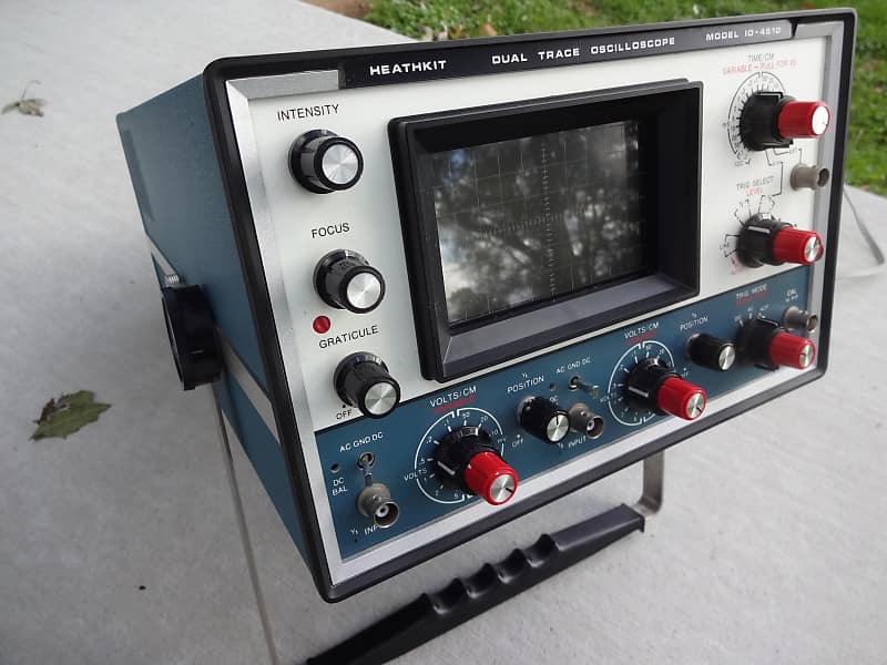
Another eccentricity of 8 inch floppy drives was that since they used A/C motors, they were sensitive to the frequency of the mains current used to drive them. Note that one of the drives in the video is prominently marked “60 Hz”. If that drive were powered by 50 Hz electricity, as used in Europe, even with a voltage adapter, it wouldn’t work because the disc would be spinning too slowly and the data rate would be incorrect. When changing an 8 inch floppy drive from one power frequency to another, you’d have to replace the pulley for the drive belt the spun the disc so it would spin at the correct rate.

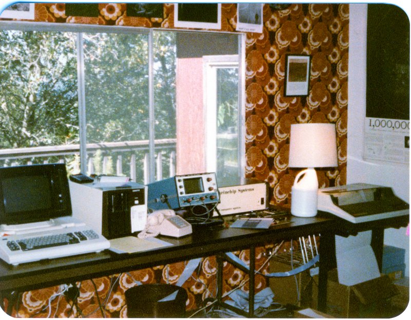
Here is a picture of the development system at Marinchip Systems Intergalactic Headquarters in Summer 1980, with a PerSci dual 8 inch floppy drive visible between the terminal and oscilloscope, to the right of which a floppy disc in its protective sleeve is visible.


We never adapted Marinchip systems to use 5ÂĽ inch floppies. Our customers had become accustomed to the 1.2 megabyte capacity of double-sided double-density 8 inch floppies, and had no interest in anything smaller. By the time 1.2 megabyte 5ÂĽ inch floppies became available, the Marinchip hardware was obsolete and power users had moved on to systems with hard disc storage.

7 Likes

My technological formidable years centered around the 3.5 inch floppy. They were neat with that spring loaded metal piece that covered the disc tape inside.

1 Like

When I was stationed at NSA during my Navy days, the space where I worked had a closet with a lot of the items in your last photo John. The blue box that sits up at an angle was of particular interest—I think that is an Osciliscope used to demodulate signals.

1 Like

Lastly—nice wall paper.

4 Likes

It’s a Heathkit IO-4510 dual-trace 15 MHz oscilloscope. My wife and I built it from a kit, and it was the only oscilloscope I owned and used between 1975 and 1993 when I retired it in favour of a Tektronix 100 MHz scope. The IO-4510 was used to develop and troubleshoot all of the Marinchip hardware, investigate hardware timings of the IBM PC and PC/AT for code optimising, debug add-ons to the IBM PC, experiment with pirate encrypted TV decoders, and repair audio gear. Apart from only one repair and recalibration in the mid-1980s, it was completely reliable over its lifetime. I still have it, but haven’t powered it up since 1992.

Here is larger picture of one from somebody selling it used four years ago.

6 Likes

If memory serves—it’s been a decade since I have had to think about this—the O-scopes were particularly useful in analyzing Phase Shift-key signals (PSK), of the 4-PSK and 8-PSK variety. In the screen is a “dot” that goes in a circle and when you have successfully match certain characteristics—freq, phase, etc—the “dot” becomes centered in the screen and you can take the information for from that and plug it into another devise—I think a spectrum analyzer—and begin stripping off the modulation. Ah memories of when I thought I was Allan Turing and Jack Ryan. Thanks John.

3 Likes

By the way that looks incredible for its age. Looks right out of the box.

1 Like

Arguably, 3.5 is a stiffy, unlike the 5.25 and 8 floppies.

4 Likes

The wallpaper is groovy!

2 Likes

I had a Dumont dual-beam oscilloscope. I added a semiconductor trigger to it.

3 Likes

8" floppies, at first for me. They were so slow and small that I managed to get my boss to buy me a 1MByte ramdisk with a battery backup. Cost $1,000. THAT was a fast MF.

4 Likes

Actually, it isn’t wallpaper. The previous owner of this house in Mill Valley, California, which we bought in 1974, decorated the walls in some of the rooms with fabric rather crudely stapled to the drywall. This room (a spare bedroom in the two bedroom house) had this 60s/70s woven fabric, while the entry hallway had a white/green/black pattern in a felt-like fabric. The latter was great, because when people visited they’d invariably feel the texture and ask, “Is it felt?”, at which point we could reply, “It is now.”

4 Likes

An oscilloscope is a general-purpose instrument that allows display of a voltage, plotted either against time (voltage vertical, time horizontal) or against another voltage in an X-Y display. The former allows measuring frequency, rise and fall time of signals, observing waveform shape (for example, to see distortion or clipping in audio equipment) or, in oscilloscopes that allow displaying two or more traces simultaneously (or alternating, as an economy measure), measure the delay between one and another, which is critical in debugging digital circuits. In X-Y mode, the oscilloscope can show the relationship of frequency and phase between two signals, allowing one to adjust two signals to the precise relationship required by the application. Using an oscilloscope in X-Y mode, you can even compose “music” that draws pictures on an oscilloscope screen. (This is simply feeding one channel of the audio to the horizontal input and the other to the vertical.)

6 Likes

That is really awesome. I wish I would have known how to do that in the Navy so I could’ve freaked out the young CTs on the ship. It would’ve been pretty awesome to learn this stuff from you guys instead of the Navy training I got. I suppose y’all have forgotten more about signal analysis than I ever knew.

1 Like

I still have a single beam model Dumont OBL-1, although it’s been stashed in the attic for at least 40 years and hasn’t been powered up for close to 50. I bought it for $10 (a couple weeks of paper route money) in high school about 1967, it came with both a regular and long persistence CRT.

1 Like

I had a leased M6800 Motorola Exorterm with 8 inch floppies (can’t remember if it had one or two, and info is scarce on the net) in the late 70s that was used for AMD2900 bit slice microcode development, that was around $1200/month. My manager at the time thought that $50 for a box of spare diskettes was too much so it only had a few diskettes, system, cross assembler, and code iirc. A few months in the system diskette died, since there was no backup we had to get another direct from Motorola which took an entire month. Saving $50 (they were bigger dollars back then) cost $1200 in lease fees plus whatever time I lost, never had a problem getting spare media after that :slight_smile:

2 Likes

Here is a geeky video from CuriousMarc explaining the fundamentals about how oscilloscope painting with music is done. Note the dual trace oscilloscope at the bottom which shows the left and right channel audio tracks that drive the horizontal and vertical axes of the X-Y display at the top.

3 Likes