OK. You guys have all asked so nicely. Here is a picture of the freshly COMPLETED BE-4 Flight Engine #1 for Vulcan’s first flight, in the stand at @blueorigin 's factory.
The powerhead of the Blue Origin BE-4 rocket engine looks very complicated. Below is a photo comparing the SpaceX Raptor 1 (left) and Raptor 2 (right) engines, which use the same liquid oxygen and methane propellants and have similar sea level thrust (Raptor 2: 230 tonnes, possible 250 tonnes in future; BE-4: 240 tonnes).
BE-4’s powerhead resembles that of Raptor 1 in complexity, while Raptor 2 has been dramatically simplified, with much less plumbing and “spaghetti” adorning it. In February 2022, Elon Musk said that the production cost of Raptor 2 was around half that of Raptor 1 due to the simplifications in design and manufacturing techniques.
The apparent difference in complexity is particularly striking since Raptor 2 uses a full-flow staged combustion power cycle, while BE-4 uses oxygen-rich staged combustion with a single preburner and turbine as opposed to the dual units employed in Raptor, with a correspondingly more complicated start sequence.
We’ll probably never know the numbers, but it would be interesting to compare the cost of BE-4 and Raptor 2.
On one of the Musk videos, there was a comment that much of the simplification of the “spaghetti” on Raptor-1 going to Raptor-2 was related to the elimination of a significant number of sensors, which had been necessary on Raptor-1 to provide the data used to improve its performance but could be eliminated from the now-optimized Raptor-2.
Perhaps there will be a similar dynamic with the BE-4.
At the risk of being accused of self-promotion*, simplification of the “powerhead” was one of the main objectives Roger Gregory and I were after in trying to update Goddard’s patents to an ultracentrifugal engine. My original motive for approaching Roger with this strategy was a combination of Walker’s strategy of “a rocket a day” (which required very cheap manufacture) and Gary Hudson’s Roton. We had some rotational stability tests run at Texas A&M. Also we had a few prototypes fabricated in an automotive machine shop by a guy who designed and fabricated custom equipment for silicon fabs. But I can’t attest to the feasibility of this design since I had limited computational modeling capability (pretty much everything getting done with TK!Solver) and we didn’t complete testing before money ran out (as it was coming out of my pocket and I had to pay lawyers for international applications).
As I recall, we were at the hairy edge of melt-down because the chamber pressure hence temperature was very high and propane’s cooling properties were limiting, even though we were running both propane and LOX as coolants. I haven’t thought much about revising the design to possibly take advantage of additive fabrication for more sophisticated topologies that might permit LOX to pick up some of the slack since LOX was a lot better coolant and we had a lot more of it flowing. I had this idea, at the time (1996) that the way to get access to space was to motivate the NASCAR culture to start doing vertical drag races (which is a phrase some others picked up on but applied in a different manner than I intended). When I was working as VP for E’Prime Aerospace in Titusville, one of the investors was heavily into the drag racing circuit, which is why I thought it might have been a relatively easy sports market to penetrate.
Roger passed on to me an idea that Gary came up with to increase the thrust to mass ratio: Surround the engines with stationary magnetic containment that served to provide image currents hence maglev forces to reinforce the walls of the engine. Since the containment isn’t under rotation (let alone supersonic rotation) it can be lighter than similar containment mass added to the rotating engine.
One of the nice things about the design is that the rotational bearing rings were of small diameter so the tangential speed-induced stresses on the internal balls were correspondingly small.
*Of course, that patent is no longer in effect so my only conflict of interest in mentioning it is non-financial.
I remember when I visited Roger Gregory around 2000 and he showed me the engine prototype he had been testing in rural Michigan. It reminded me of a brake drum assembly from a 1950s U.S. automobile and I mentioned something about “flight weight”. Roger reminded me that with the extreme acceleration of the propellant from the spinning of the engine, the boilerplate I was holding was a flight weight engine if it performed as the models indicated it could.
As I recall, in our conversations he was contemplating fluid bearings for the critical rotating joints. I don’t know if that would have worked in the vibration environment of combustion or how it would handle start-up and stop and restart for applications where that was required.
Still, it’s one of those paths not taken which remains open for anybody who wants to change the game.
Rear Brake Drum/Hub for 1950-1952 Chrysler Royal - Saratoga - Windsor
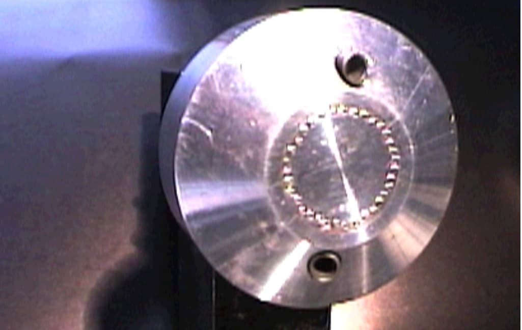
The prototype:
I should probably explain the suspiciously small number (only 8) of cooling channels in the patent drawings. That’s what my TK!Solver model said we could get away with due not only to the high thermal conductivity of the aluminum but also the fact that the model said the stupendous Coriolis forces in the liquid channels (due to both forced and free convection as well as linear flow) would cause the liquid to spin inside the channels at enormous speeds – resulting in ridiculously high thermal transfer. I’ll admit I was never very comfortable with what the model was telling me, since modeling such complex fluid behavior in TK!Solver is pushing credulity – but that was what it told us.
Roger later decided it was not adequate and he added a lot more cooling channels to his modifications:
My concern with that modification is, again, that it was never put through adequate numeric modeling. Something like a COMSOL Multiphysics model is probably in order. My suspicion is, as I said previously, that additive manufacturing of the engine is probably also in order to modify the topology so the LOX flow offloads cooling from the propane flow.
As for fluid bearings, I’m pretty sure Roger looked into that adequately but my recollection was that the Texas A&M mechanical engineering guys, in possession of a prototype with silicon nitride bearings, said the safest way of stabilizing the rotation was placing loads on the top and bottom of the axis in opposing directions (perpendicular to the axis of course). I vaguely recall Roger saying that this wasn’t necessary due (again IIRC) to the fact that any imbalance would result in a greater flow rate out of the favored injectors thereby lowering the liquid level in the feeding channels to reach equilibrium. Any asymmetry in injector flow rate to the annular combustion chamber would be immediately evened out by the enormous Coriolis forces arising from free and forced convection. That’s something else that needs a preliminary numeric model thence a physical spinup test with liquid flow through the engine.
Something else that is “suspicious”, but is almost certainly correct, is the tiny expansion nozzle.
One has to keep in mind that this engine is operating at a much higher pressure* than people are used to thinking about. This is one of the reasons it is able to achieve such a high thrust to weight ratio.
In a system with a large number of such engines operating in parallel, there is an additional quasi-aerospike effect rendering large expansion bells less necessary and possibly even making them undesirable.
I suspect this is something Musk is taking advantage of with his large number of Raptors operating in parallel.
And while things are coming back to memory after a quarter century, I may as well mention that PROPEP said that at such high temperatures and pressures propane+LOX combustion could use some help from water injection. This would reduce the effective thrust-to-weight ratio of the engine but it could also dramatically increase the regen cooling capacity.
*Roger’s “longer diatribe” page gives 2 different chamber pressure numbers: 2500 psi and later 11,340 psi. These are for different engines, the first one being a prototype that has a thrust to weight ratio of 500 despite the lower pressure – probably because the weight doesn’t include the expansion bell that he says is necessary at least for injectors spinning at 300m/s. The 11340 psi figure is for an engine with 600m/s injectors. The higher the chamber pressure the more one can constrict the flow with the same in-engine expansion nozzle, but at the cost of lower regen coolant (fuel/LOX/water) flow hence higher heat load per coolant. I recall at one point thinking there could be complete expansion with the in-engine nozzle expansion at least during ascent, with sufficient specific heat capacity (such as high water flow).
It has to be noted – this vehicle looks rather similar to the DCX Delta Clipper resuable rocket that was successfully tested in the early 1990s. Thirty years ago! An engineer starting his career when the DCX first flew will by now be thinking very seriously about his retirement.
Gary Hudson’s Rotary Rocket Roton design resembled the DC-X, but it was radically different in almost all particulars. While the DC-X used liquid hydrogen/oxygen propellants and sea-level modified versions of the expander cycle RL-10 engine, the Roton used LOX/kerosene propellants in a spinning aerospike engine with multiple combustion chambers where propellants were pumped by the centrifugal force of the engine’s rotation. This is (very) similar to the Bowery/Gregory patent cited in comment #4 above.
Re-entry would dissipate heat by releasing water through the base, which would absorb compression heating and create a layer of steam that would insulate the vehicle from heat. For landing, foldable rotors would be extended from the top, spun up by tip rockets, landing like a helicopter.
Gary Hudson produced a nice video to demonstrate the concept around 2000, but I can’t seem to find it on-line today. Here is a longer video from Hazegreyart showing the launch and landing concepts.
An actual vehicle was built to test the helicopter concept and its ability to be flown in the atmosphere. Here is a test flight at Mojave airport in 1999.
It was far—very far—from clear that Roton would have worked. Single stage to orbit is extraordinarily difficult, especially with LOX/kerosene propellants. The rotary engine was intended to produce a very high specific impulse of 355 seconds with thrust to weight ratio of 150, but it had never been demonstrated, even at sub-scale. In 1999, Rotary announced it was abandoning the rotary engine in favour of a version of the Fastrac engine under development by NASA: this reduced the development risk but made achieving the performance needed for single stage to orbit even more implausible.
The reusable re-entry system with water injection had never been demonstrated in flight and was extremely vulnerable to disruptions in water flow, which would result in a catastrophic burn-through in seconds.
The helicopter landing system was to be demonstrated by the Atmospheric Test Vehicle whose flight was shown in comment #10. While the vehicle flew, pilots found it extraordinarily difficult to control and the shape of the fuselage made it impossible to see the ground, requiring them to judge altitude by radar.
Some innovations just don’t work well enough to pursue, and there’s nothing wrong with this. Evolution progresses from extinction to extinction.
The entire craft had a low rotational inertia, and torque from the spinning rotor blades made the body spin, unless counteracted by yaw thrust in the opposite direction.
— Dornheim, Michael A., “Roton Hops Off Ground.” Aviation Week & Space Technology, August 12, 1999, p. 36.
The space-going version would have required three-axis reaction control thrusters anyway, so these thrusters could be used during the landing to keep the craft from spinning around its vertical axis. The rotor blades on the Roton were powered by tip jet rocket engines. These engines do not impart a rotational torque to the airframe in the way a rotor powered by an engine turning the rotor hub would do. This means the only counter-torque that needs to be applied is to cancel torque due to friction in the hub, which is much lower than that of a centrally-powered rotor.
The Hiller YH-32 Hornet, for example, which used ramjets on its rotor tips, required no tail rotor to control counter-rotation.
The real lost opportunity involving the DCX is one of the more perverse events in the history of aerospace to which I was a witness – and victim:
During our effort to force NASA out of competition with the private sector, libertarian-leaning Rep. Dana Rohrabacher was an important supporter and his space activist staffer, Tim Kyger, was our primary liaison. Tim told me that my testimony on the the issue was among the most powerful of any testimony before Congress he’d seen – which at the very least indicates how enthusiastically supportive Rohrabacher’s comitatus was.
After I gave that testimony, my experience with the various privately capitalized launch service companies brought me into contact with E’Prime Aerospace of Titusville, FL. They had, somehow, managed to get control of the MX missile production line, and had a stripped down version to make it easier to manufacture. Since operational expenses had been minimized in the MX design, and operational expenses were dominating launch service costs, and risk had been mitigated by the military, I got really interested. They needed a customer. The customer they had lined up was Norris Satellite – a company out of Lancaster PA that had made its money with satellite broadcast of TV preachers among other things – and they wanted to orbit a Ka-band satellite that would provide digital service.
There were no Ka-band satellites back then. So then I became interested in the licensing process for opening up new bands. That’s when E’Prime, noting my past political success hired me as VP for Public Affairs – in part to help facilitate the Ka-band license through.
This was all late 1991 to early 1992.
We did manage to make good progress on that front. We needed additional capital so we had a meeting with potential venture financiers in the LA area (broadcast TV). I was in attendance.
The meeting seemed to be going well, but then something happened…
At noon break the VCs broke off the meeting.
The reason?
A company in Rohrabacher’s Long Beach district had just been awarded capital by the DoD to construct a single stage to orbit launch vehicle which came to be known as DCX.
Around the same time Roger and I were awarded a patent, Williams International patented a related rocket engine with quite lot more parts – although still fewer than most engines, including SpaceX’s Raptor 3. They are based out of Michigan. Although in a different part of the state, Roger’s family farm was in Michigan, where Roger tested the prototype rocket engine circa 1998 until the sheriff came out and stopped him.
Williams International was a lot better funded than we were and may have actually developed theirs with government funding. This is their engine (that doesn’t seem to have been deployed by anyone):
At the advice of a retired Honeywell pump guy I met by chance recently at a July 4 event, I figured it wouldn’t hurt to put together a request for “ballpark quote” on a multiphase CFD (no combustion) for the original design.
I’m sending this out to any company that might provide one:
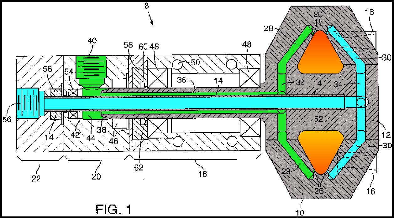
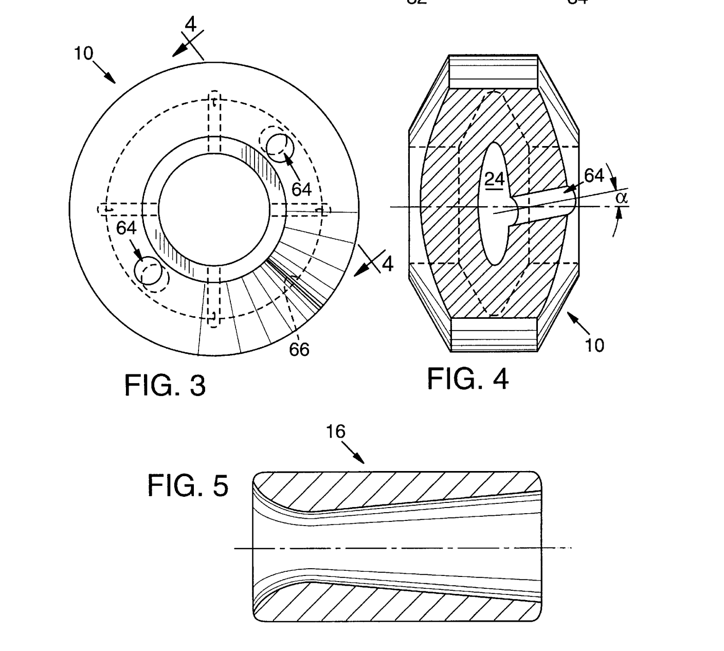
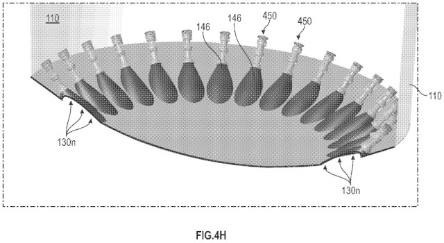
This is a side view of Fig. 1 in the patent, LOX inlet on left, LPG inlet hidden on opposite side:
Azure is LOX
Green is LPG
Orange is combustion Gray is co-rotating aluminum structure
26 are injectors
16 are CuW delaval nozzle inserts – dotted outline (embedded in the aluminum)
The inlet boundary conditions set on the left of the aluminum structure would be for LOX and LPG.
The outlet boundary conditions set on the right would exit delaval expansion into vacuum.
The combustion chamber (orange) heat input equivalent to combustion would be outer circumference.
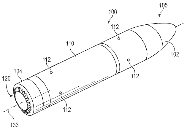
Systems and methods for a fully reusable upper stage for a multi-stage launch vehicle are provided. The reusable upper stage uses an aerospike engine for main propulsion and vertical landing. A heat shield can include a plurality of scarfed nozzles embedded radially around a semi-spherical surface of the heat shield, wherein inboard surfaces of the plurality of scarfed nozzles collectively define an aerospike contour. The heat shield can be actively cooled to dissipate heat encountered during reentry of the upper stage.
Blue Origin’s answer to Starship? If this is developed on Blue Origin’s schedule to date, start looking for it post-2050. Aerospike engines have been considered for decades as a way to optimise rocket engine performance from sea level to vacuum for launch vehicles, but this is the first time I’ve seen it proposed for an upper stage to start in vacuum and return to a vertical landing on Earth.
The minute I saw BlueOrigin go into a “public private partnership” with the old guard on their engine development, I basically wrote them off. Although it is on a spectrum of government capital to private capital technical risk management, the toxicity is such that one may as well think of a sandwich that is on a “shit-meat partnership” spectrum.
Looks like several thousand dollars to do the mesh model and run the initial CFD. Roger thinks the inlet to the coaxial pre-swirl pipe will require an inducer to avoid cavitation. I vaguely recall doing that calculation and thinking we could get away without it but he’s done more recent calculations with better tools. The old pump engineer thinks an inducer is probably necessary but that it’s ok to use a high pitch screw and permit cavitation at the inducer’s leading edge even though it erodes.
So I’m thinking maybe the thing to do is just write some code parameterized by various design features to generate the mesh and do a number of very rough cut OpenFoam runs to adjust the design before blowing money on professional CFD.